Materials
Young's Modulus: A measure of the stiffness of a material.
There are 4 main types of materials: Metals, Ceramics, Polymers, and Composites.
There are 4 main types of materials: Metals, Ceramics, Polymers, and Composites.
- Metals: Apart from being extremely sturdy and electrically and thermally conductive, Metals are malleable (tend to not break from deformation), vulnerable to corrosion (as they have non-localized electrons), and typically more costly than other materials. They tend to have a high Young's Modulus from their rigidness and ability to maintain shape. (Ex. Brass, Copper, Steel)
- Ceramics: Ceramics are compound materials with corrosive resistance that are tough to reshape. Ceramics can be insulators, semi-conductors or ferro, and are usually chemically non-reactive. Along with metals, Ceramics typically have a high Young's Modulus, but they have a lower fracture toughness than Metals. Ceramics can also be classified into Oxides(Ex. Zirconia, Alumina, Ceria), Non-Oxides(Ex. Nitride, Silicide, Boride), and Composite Materials(Ex. Particulates, Fibers, and combinations of oxides and non oxides).
- Polymers: Polymers are large molecular compounds that are unstable at high temperatures. While Polymers have a low Young's Modulus, they are cheap and lightweight, so they are often used in the materials world.(Ex. Polyethylene, Polyvinyl Chloride, Polytetrafluoroethylene)
- Composites: Composites are a combination of different materials that are meant to strengthen the overall functionality of the end result. Composites do not completely merge together and can exist naturally or artificially.(Ex. Ceramic Fiber, Plywood, Polymer Matrix)
Stress
Stress is the force applied to a certain cross-sectional area that tends to deform the object. An important term to know is engineering stress, or nominal stress, which differs from the true stress in its approximation of the actual cross-sectional area by using the original cross-sectional area.
All you need to know for now is that the engineering stress-strain curve depicts a decrease in the slope of the stress vs strain graph, which indicates an underestimate of the true stress strain relationship.
TYPES OF STRESS
Tensile Stress is the applied stress that stretches the object in the direction parallel to the axis.
Compressive Stress is the applied stress that compresses the object in the direction parallel to the axis.
Torsional stress is the applied stress that causes rotational deformation through a torque or moment force.
**Note the only differences between the stress formula for compressive/tensile stress and shear/torsional stress is that they use different variables to represent stress and that the forces used in the formulas have different direction.
Compressive Stress is the applied stress that compresses the object in the direction parallel to the axis.
- The formula for both compressive and tensile stress is σ=Ft/A, where F and A represent Force and Area respectively.
Torsional stress is the applied stress that causes rotational deformation through a torque or moment force.
- The formula for both shear and torsional stress is τ=Fs/A, where F and A represent Force and Area respectively.
**Note the only differences between the stress formula for compressive/tensile stress and shear/torsional stress is that they use different variables to represent stress and that the forces used in the formulas have different direction.
Strain
Strain is the response of an object to the applied stress (force). This is defined as the deformation in the direction of the applied stress over the initial length of the object. In the strain–stress curve, strain is the x-axis that is directly proportional to stress. This can be visualized as a form of Hooke's Law.
TYPES OF STRAIN
Tensile Strain is caused by tensile stress that increases the length and shrinks the width.
Shear Strain is caused by shear stress.
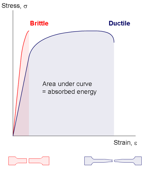
Stress vs Strain curve
Proportional limit (Point A): The point in the stress-strain graph up to which stress is directly proportional to strain.
Elastic Limit (Point B): Elastic limit, or the yield point, is the stress value beyond which material no longer behave elastically but rather is permanently damaged. Material with stress below the elastic limit exhibits elastic behaviors while material with stress beyond the elastic limit exhibits plastic behaviors.
Toughness/Resilience: Both the energy found by integrating the area under stress-strain curve. The one difference is resilience integrates from the origin to the elastic limit while toughness integrates from the origin to the fracture point.
Types of Materials
Brittle: when subjected to stress beyond the elastic limit, brittle material breaks without significant plastic deformation.
- Ex. Iron, concrete, and glass
- Ex. Aluminum, copper, and steel
Atom Structures
|
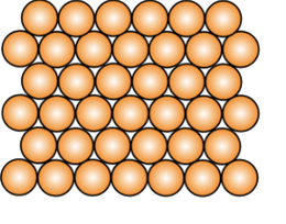
Crystalline Materials
|
|
|
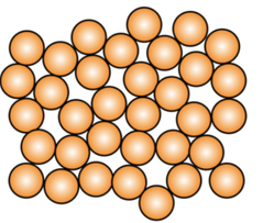
Noncrystalline Materials/Amorphous
|
|
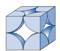
Metallic Crystal Structure
Metals have the simplest crystal structure and tend to be densely packed because
- Nearest neighbor distances tend to be small in order to lower bond energy.
- Electron cloud shields cores from each other.
- Metallic bonding is not directional.
- APF= Volume of atoms in unit cell/volume of unit cell
TYPES OF METALLIC CRYSTAL STRUCTURE
|
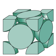
Simple Cubic Structure (SCS)
|
|
|
|
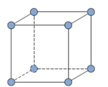
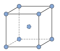
Body Centered Cubic Structure (BCC)
|
|

|
|
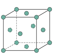
Face Centered Cubic Structure (FCC)
|
|
|
Ceramic Crystal Structure
Ceramics are inorganic and non-metallic materials that are commonly electrical and thermal insulators, brittle and composed of more than one element
FACTORS THAT DETERMINE CERAMIC CRYSTAL STRUCTURE
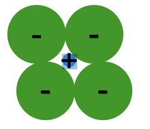
1. Relative Sizes of Ions (formation of stable structures)
- Maximize the number of oppositely charged ions neighbors.
- Cations, or positively charged ions, wants maximum possible number of anion, or negatively charged ions, nearest neighbors and vice-versa.
- Stable ceramic crystal structures occurs when anions surrounding a cation are all in contact with that cation.
Unstable structure
|
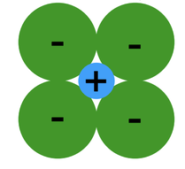
Stable structure
|
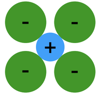
Stable structure
|
2. Maintenance of Charge Neutrality
- Net charge in ceramic should be 0.
- Charge balance dictates chemical formula
- Ex. Ca2+ and F- form CaF2
